|
Technical Terms
|
Description
|
|
Technical Terms |
Explanation
|
|
Optic axis of beam
|
|
Standard detected
object |
That indicates the standard detected object, which is to
determine the basic specifications in the reflection type
sensor. Generally, it is white and lusterless. Use relevant
detected object (for example, the slice) to the sensor
for special purpose. |
|
Detection axis
|
|
Min detected
object |
That indicates the smallest object, which can be detected
by sensor under a certain condition. To correlation type
and mirror reflection type, that indicates opaque body
(wholly light sheltering). To reflection type, that indicates
the corresponding value of iron wire or copper wire. |
|
Detection
distance
|
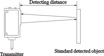
Through-beam type
Stably set distance between transmitter and receiver

|
Repeated precision |
That indicates the error of response position when
repeating action under a certain condition.
 |
Retroreflective type
Standard setting distance between sensor and reflector
(omit “0”on the occasion with “0”)
|
Response time |
That indicates the delayed time of outputting ON or
OFF signal after the detected state changes.
 |
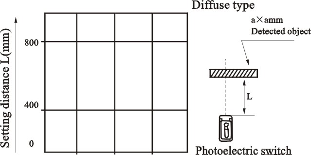
Diffuse type
The max stable detection distance of detectable
object, generally white matt paper
(omit “0”on the occasion with “0’)
|
Intensity of
illumination of
operating
environment
(resistance to
mixed
astigmatism) |
That indicates max, intensity of illumination, which
doesn’t result in error action, expressed by intensity
of illumination of photorecetor photic surface.
 |
|
Technical Terms
|
Description
|
|
■ Cautions
To through-beam type and retroreflective type
The set distance should be less than the detection distance stipulated
in the operation instruction. Because of keeping a room, although it can
work when the set distance is bigger than the stipulated detection
distance, the performance cannot be guaranteed. In addition, please make
sure to keep certain room in the bad environment with rubbish and dust
when setting a distance.
■To diffuse type
The detection distance shown in the specification manual is in
accordance with standard detected object. Actual detection distance will
change in pace with the change of the size, color, surface evenness of
detected object. Please ensure the stipulated room when set distance.
According to the change of detected object size and variation regulation
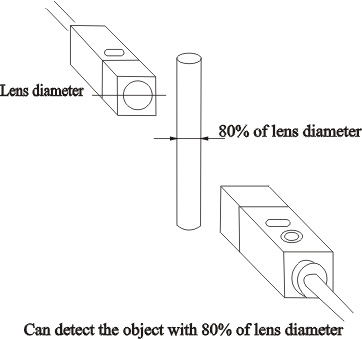
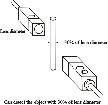
of detection distance, bigger detected object, bigger reflection volume,
longer detection distance. But when the size of optic receiving surface
is bigger than the size of the detected object, the detection distance
won’t increase even if the object size increases again.
The difference between different detection
distances of the detected
object (Apply to diffuse type)
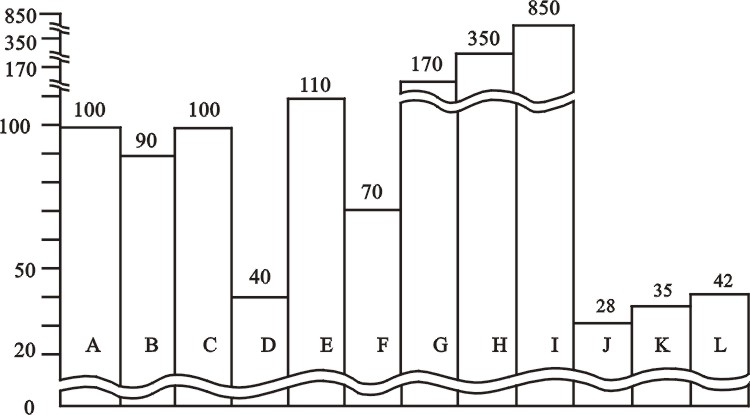
A. White matt paper (reference)
B. Natural color carton
C. Veneer
D. Black matt paper (Grade 3 glossiness)
E. Glossy vener (Natural cream-colored board, brown propylene board, red
ethylene synthetic board)
F. Grey ethylene synthetic board
G. Green glossy rubber board
H. Alboard
I. Reflector or reflecting board
J. Rusty iron barφ10
K. Black cloth
L. Dark blue cloth |
|
|
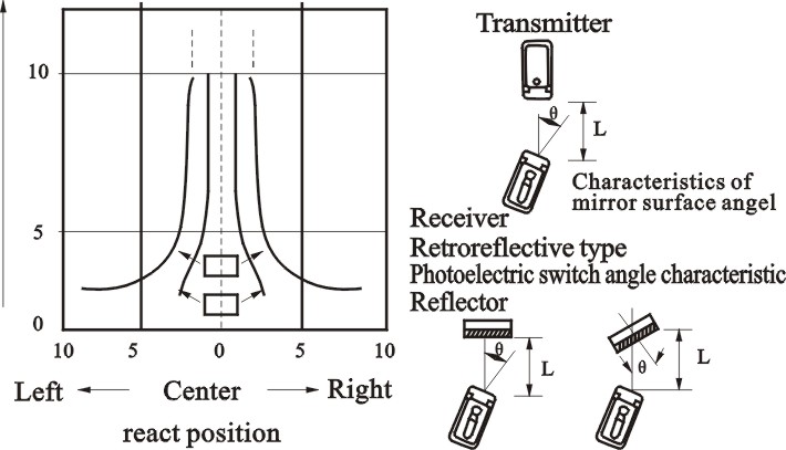
To through-beam type and retroreflective type, move
from right to the centering of left direction within
each setting distance to gradually reduce the angle.
That is shown by locus diagram of sensor action
response angle (under max sensitivity state)
|
|
The characteristic of detected object
size and detection distance
|
To diffuse type, because the size of detected
object affects detection distance, this diagram
is useful to determine the stable detection
distance according to the size of detected object.
The sensor with sensitivity button is to turn the
sensitivity to the relevant position of max.
Detection distance where exactly detecting the
standard detected object.
|